Hello fellow Reviteers. I would like to announce the inception of Buro Smith Consulting. BSC specializes in BIM/CAD consultation and management in regards to the true BIM process as well as Integrate Project Delivery (IPD).
We not only focus on consulting but also the educational format as well. We strive to educate our users not only on how to operate the program but how to manage and integrate it into their current workflow. The Digital Architect Series has been created in order to maximize each client's investment as well as their create an efficient workflow that best suit that project's need. For more information, please visit us at www.burosmithconsulting.com.
Tuesday, July 7, 2009
Introducing Buro Smith Consulting
Monday, April 20, 2009
Green Templates Part II: Revit Architecture to Ecotect

With the onslaught of "Green" packages integrated into the BIM process and workflow, many users do not realize that the essential part of the data starts from the model itself. Of course you need a model to dictate your outcome in Ecotect or Green Building Studio, but the way we manage and set up our model needs to be refined prior to our exportation. By setting up our model at the very early stages of our design, we ensure that our readings in our sustaibable packages are accurate and reliable.
For this blog, we will focus on integration with Ecotect and Revit Architecture 2010. Listed below are the steps accompanied by images to aid in the process.
1. Select the MANAGE tab from the ribbon. Then select the PROJECT INFORMATION button. This will bring up the Instance Properties dialog box. In the dialog, select the EDIT button from the Energy Data data cell. This will take you to the Type Properties dialog box for Energy Data.
2. Enter in the necessary information for building type, postal code, ground plane, etc. You can omit this step prior to exportation and enter the data within Ecotect as well.
3. Next, select the HOME tab and then select the Room and Area pulldown>Area and Volume Computations.

4. Make sure that within the Area and Volume Computations dialog and under the Computations tab that the "Areas and Volumes" radio button is selected. Click OK. This sets the Revit model to compute both.
5. Place in your room and area tags and enter the information needed into each room tag. Information such as room name, ceiling finish, number, et cetera can be modified.
6. Place a section line across your model and go directly to that view.
7. If you want to place in a color scheme, place one in. In any case, working with both the plan and the section view open helps to visualize the next few steps. You will want to make sure that your roof is your bounding element and that your ceiling is not. If you have plenum space above or any space in your model that is not properly accounted for, Ecotect will produce inaccurate computations resulting in misleading information for LEED credits.
8. Make sure your room boundaries exceed the bounding component to ensure Revit computes the entire volume desired.
9. Select the Revit Icon at the top left and export the model to gbXML format. With 2010, you will open the ExportgbXML dialog box where we can also modify the project settings and its details and even isolate a desired room.
10. Click on Export.
11. Open up Ecotect Analysis 2010 and select from the FILE pulldown menu>Import?Model/Anaylsis Data.
12. Make sure that in the dialog box that appears you set your Files of Type to XML. Select your gbXML file.
13. The Import XML data dialog box opens up. Here you can specify how each room element comes into Ecotect. Click Open as New.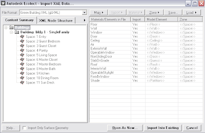
14. Run a series of tests in Ecotect to obtain your desired results.
Do keep in mind that these Green sustainable packages do not automatically certify your project for LEED accreditation but merely guide you in your process and workgflow to attain those credits.
I will focus more in detail with our sustainable packages as well as the utilization and implemtation of certain techniques in future posts. Stay tuned for more in this series.
Tuesday, February 17, 2009
Green Templates Part I: Indoor Analysis and Glazing
As Kermit once said, "it's not easy being green". How true this quote is, especially within the design industry. How do we become "green"? How can we begin to implement green practice into our Revit projects? Do we need to purchase Ecotect, IES, et cetera?
Although those packages will help a great deal in pointing you and your firm in the right direction, we can start to follow the green bricked road to the Emerald City (also Green!). Before we even export our model into an analyzation package, we can fashion our Revit template to provide a data path that will direct us even before getting to that green road.
The use of schedules and its manipulation will display and lay out the necessary information we need to adjust and modify the design. Lets take a quick look.
We have to set the model up correctly at first by using the Room and Area tools. Make sure your room computations are set to "areas and volumes". This is will give us an accurate calculation. 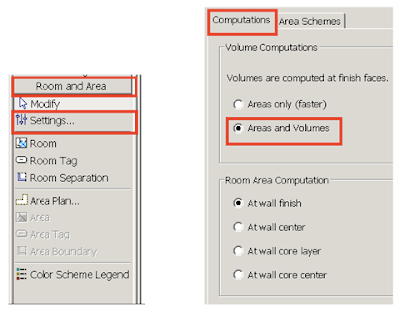
Once that is set, we can then apply parameters to window systems as well as scheduling properties to calculate the information. The NORTH, SOUTH, EAST, and WEST parameters were added to be contained only to windows and curtain panels.
The formulas utilized in this schedule are:
Window Area Width * Height / 1 SF
Glazing Area of Room % of Window Area: From Room: Name
Overall Glazing Area Window Area / Glazing Area of Room
Glazing Percentage of Room Overall Glazing Area / Room Area
Room Area From Room: Volume / From Room: Unbounded Height / 1 SF
Glazing Multiplier if(North, 0.05, if(South, 0.15, if(West, 0.07, if(East, 0.07, 1))))
Overheat Integer if(Glazing Percentage of Room < Glazing Multiplier, 1, 2)
Overheat if(Overheat Integer = 1, "no", "yes")
Once that is set, the information can then be calculated to give you the desired outputs. Again, remember that Revit does not qualify your project for LEED accreditation but merely points you in the right direction.
Tuesday, February 3, 2009
The Digital Architect Series and 4D Planning

The Digital Architect Series was designed by Microdesk to facilitate and improve the design workflow as well as provide flexibility to your firm. If you utilize more than one program in your firm, chances are you are a prime candidate for the Digital Architect Series (DAS). DAS incorporates all aspects of the design workflow with existing, emerging, and future technologies to help alleviate overhead costs, downtime, and miscommunication.
With the advent of BIM technology and the Revit platform, more and more firms are adopting this new form of design and modeling. Taking information modeling to the next level is anyone's guess. We have seen other products, add-ons, and so on being mixed in with the BIM craze. Harnessing the BIM movement is up to you. Do you merely just want to implement BIM and totally abandon your old workflow? Of course not.
The Digital Architect Series realizes the need for every designer to evolve not just in technology but to be truly ahead of the rest, you need to evolve your workflow. DAS incorporates all Autodesk products other product family lines to create a smooth and efficient workflow that will help your company obtain higher revenue, lower overhead costs, and develop and modern approach to the workflow process. So much informaiton is lost in translation between programs that most times, you end up working on something that was already done.
Think about going from Google SketchUp to Revit to Ecotect to Navisworks to Primavera. The interoperability can sometimes cause headaches but realizing the your path and planning out an effective and efficient solution with DAS will help you get there. For more information on DAS, please visit www.microdesk.com.
I mention in the title of the idea of 4D. 4D design has and is a main component in project planning and workflow, but also can serve on various different levels in the BIM environment. A section of DAS focuses primarily on the aspect of 4D. Primavera is the leading program in 4D and Microdesk has implemented its use within the DAS. It is now possible to take a series course of Google SketchUp to Revit to Ecotect to Navisworks and finally to Primavera. A solid workflow that finalizes with 4D.
Primavera is the leading project and program management solution provider to the AEC Industry. No matter the size of a project, Primavera enables AEC organizations to effectively manage time, costs, resources, contracts and changes in a single solution. Primavera’s Integrated Project Management (IPM) provides each project participant with anytime, anywhere access to their project information. For more information on Primavera, visit www. primavera.com.
Microdesk is an authorized reseller of Primavera software!
Wednesday, July 30, 2008
All Hands On Deck!
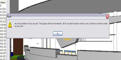
Ah those lovely messages that appear for some odd reason. You may be working on a model and WHAM! Revit has encountered an issue and flatlines. Here are a few things you can do to remedy the issue.
1. Audit the file. As a file is audited, the data is reviewed and problems that were found within the model are corrected. You can run an audit on a file within the Open dialog box. Highlight the file you wish to open within the dialog and located on the bottom of the window, you can check "audit" to do so to the file. If you are working with worksets, make sure that everyone has relinquished and exited all sets.
2. Review your warnings dialog. Go to the Tools pulldown menu and select the Review Warnings option. By checking this each time, Revit will address each issue and provide a solution.
3. Purge any unused items. A poorly created family may be the culprit in all of this or a defected line type or even XREF. Purging rids these gremlins. To access the Purge command go to the File pulldown menu and select the Purge Unused option.
Monday, July 28, 2008
Revit Displays
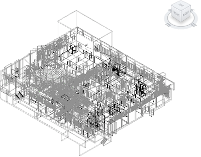
Do you ever get those Revit gremlins that come in over the weekend and muck around your projects, desk, computer, et cetera? "Such and such was working Friday but today all hell has broke loose. No one has touched the file since I left and all of a sudden, my model doesnt display correctly". I have had numerous clients call in for support on this various issue. No matter what the view is set to, the user will try to set the model to hidden line, shading, or wireframe and yet nothing changes. The model is still displayed as wireframe (in most cases I have come across). This scenario is usually accompanied by a system crash as well. It seems that the view is corrupt in some way. A simple fix is warranted don't you think? And why not.
Go to the 3D view in the Project Browser and right click on the view name. Select to delete the view. Go to the "Default 3D View" icon located View toolbar to create a new 3D view. Now you should be able to adjust the display setting without error.
Friday, July 18, 2008
Crossing Over
The slow death of the Revit platform and BIM in general has come to somewhat of a halt. As I have worked with Revit for some time now, I remember in the beginning that many firms were slow to react to the change in the design process and when they did accept or "try" Revit, they became so frustrated with the program and shelved it. As I knew of Revit's full potential back in the early days, many were quick to write of the program as a fad.
As the years have passed, that misconception has dwindled in numbers. More and more firms are adopting BIM as if it were second nature. How has it changed from five years ago to now even? Why are people that were shunning BIM now adopting it?
Its quite simple. Revit in general has created a full line of products ranging from Revit Architecture to Revit Structure and beyond. Believe it or not, but Revit as a platform series helps the overall process by having team members on the same working model. If you are concerned about DWG files then no worries. Revit also works well with many different CAD formats. There are more third party applications now than ever which give a user a wide array of usefull tools ranging from rendering add ons to green architecure and analysis tools. More and more tools are added with each new release helping to facilitate efficient workflows but also greater ease of use. Family components, which are similar to AutoCAD blocks, are being developed by comanies such as Kohler and Anderson to name a few. The AIA took less that 2 years to develop a National BIM Standard whereas in comparison took over 12 years to develop the AutoCAD Standards. Firms are beginning to realize the full potential of BIM and thus realizing their full potential as designers as well.
At first the learning curve is steep in that it will take some time to get used to new commands, procedures, workflows, layouts, et cetera. I generally advise clients that you will be comfortable with Revit after 1-2 projects. I see this at every session I train where users can become frustrated very easily. However, with proper nurturing and consulting, these same users will eventually become the "power users" of the firm. So if you are thinking that Revit is something of a fad, I implore you to further research this topic by click here. This link is to an AUGI post. The first post lists an array of sites that detail each concern. I hope this helps you on your quest. Until next post.......
Monday, July 7, 2008
Photoshop and Design Part Zwei

I mentioned before in a previous post of the potential for Abobe's Photoshop CS3 being implemented into the design world. As a continuation of the earlier post and throughout the past few months since then, I have heard many grumblings in almost all the AEC firms I have worked with in regards to creating a more vivid presentation and representation of a model. As more and more inquire about different rendering applications and incorporate those into the design process, I always mention the use and need to Adobe Photoshop and always get a serious inquiry about training and implementation.
Microdesk has announced as of July 1st that they will now be offering consulting and training services in this field. All in all there will be five courses that range from the basics, intermediate, and advanced, to custom courses and industry specific classes such as Photoshop for interior designers. Each class is named after a Greek/Roman column style that is sure to catch the eye of any would be client. For more information, you can read the release from Cadalyst's page. Click here.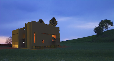
Saturday, July 5, 2008
Ecotect Is Here To Stay
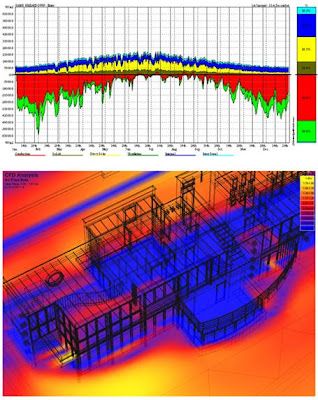
With all this talk about "green" architecture, more and more vendors out there have begun to if not already test the waters with various different "green" programs. There are great programs out there that can literally calculate every aspect of LEED and then some. In one of my previous posts, I mentioned Green Building which is a great little program to measure a buildings ability to live in a symbiotic relationship with its niche rather than parasitism. So now we come yet to another milestone in the world of the AECO industry. Autodesk has bought Ecotect. Having experienced Ecotect in the past, I can truly say that this program is what this industry needs to be eco-conscious. It is my professional opinion that Autodesk will not only continue to pour in on the R&D side of things with Ecotect, but they will also make this program the industry standard. Like AutoCAD some 20 plus years ago and now with the Revit platform, Ecotect will eventually takes its place in the AECO industry. There will be others believe me, those that try to mimic Ecotect, but like we all know, Autodesk will have had an already commanding lead.
As their website describes, "Ecotect is a complete building design and environmental analysis tool that covers the full range of simulation and analysis functions required to truly understand how a building design will operate and perform. It finally allows designers to work easily in 3D and apply all the tools necessary for an energry efficient and sustainable future."
If that doesn't sell green, then what does? For more information on Ecotect, click here.
Monday, June 9, 2008
Are You Green?
This month, the Jacob Javits Center in New York City, will be hosting BuildingsNY. If you are in the area and can attend this gala, I highly suggest it. This show will display ever product imaginable as well as services for those in the residential and commercial industry. For more information please click here BuildingsNY.
Friday, June 6, 2008
Room Tags That Display Ceiling Height

Room tags can very static at times in Revit. At times you may want certain information displayed within a tag. Whether it is the material finish, the height of an object, the manufacturer, room names, or in our case ceiling height, all this can be done by manipulating and editing the existing family. In this scenario, I wanted to create a roo m tag that will pull in information and display the ceiling height property. He are the steps to create the above image.
Since you can not create a room tag that directly links to the ceiling information, you will have to finagle the set up.
SHARED PARAMETER
1. Set up and create a shared parameter. File>Shared Parameters...>Create.
Here you will create the TXT file and where that file is to be saved
2. Create a parameter group while you are in the EDIT SHARED PARAMETERS dialog box.
3. Create a new PARAMETER via the button on the right of the dialog
4. Within the PARAMETER PROPERTIES dialog box, enter a name, keep the discipline set to Common, and se the type parameter to LENGTH
5. Click OK to get back to the project
PROJECT SETTINGS
1. Go to the Settings pulldown>Project Parameters... Click ADD within the dialog box, and within the Project Parameters dialog box, the top portion (Parameter Type), select the SHARED PARAMETER option. (everything will gray out and press the SELECT button)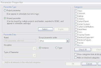
2. Select your shared parameter you just created and click OK
3. Specify the the parameter be grouped under OTHER and set to either Instance or Type.
4. Over in the right pane of the Parameter Properties dialog box, check the category you want the property to be associated with. (Rooms)
5. Click OK twice to get back into the project.
6. Use the room tool and place it into the confined area with tag placement.
7. Click on the room object and go to the element properties and under the OTHER category, enter in the height for your ceiling.
EDITING THE FAMILY
1. Click on the room tag and select the EDIT FAMILY option at the top of the design bar.
2. In the family editor, select the LABEL tool
3. Once the SELECT PARAMETER dialog box appears, choose the ADD button and click SELECT and add your shared parameter.
4. Click OK until you get back to the family editor. Place your label in the desired area.
5. Save your family and load into your project.
6. The tag will now display your ceiling height.
Remember that the tag is not actually pulling data from the ceiling itself but you will manually go to the element properties for the room object and enter that data in.
Friday, May 30, 2008
Incorporating BIM

Are you and your firm thinking of transitioning from the static 2D environment to a more robust BIM model? Chances are you are thinking about and so are thousands of other firms out there. As I described the benefits earlier in an older post, click here, that is not where the issue lies. A lot of firms that do take the dive into BIM, execute it in a manner that is not feasible nor is it efficient on many fronts. In many instances, I describe this whole process as a construction site. A project is not completed all at once but rather different phases. Hence, deploying a program such as Revit is in many way like a site. It must be built up.
I have consulted, implemented, and advised many firms throughout the years and cannot tell you how many times firms will take it upon themselves to implement, train, and execute BIM into their office. Many cases end up as an architectural and planning abortion. More money is wasted through support issues alone.
For those of you who have just recently adopted BIM, I strongly adivse you to contact your reseller (Microdesk-some shameless promotion was coming :)), and I emplore you to hire consultants that have knowledge to do complete this daunting task. It is no longer a click and install procedure but rather it must be a methodical process.
1. Implement and deploy Revit in a manner which best suits your practice. Network or single deployment
2. Pick a small team, no more than 5-6 people who will advise the rest of the firm and will start with the pilot project.
3. ENROLL IN TRAINING COURSES. I can not stress this enough. So many people want to train themselves and in the end more issues arise. Trust me!
4. Work with consultants-Microdesk- we well be able to shadow and support you through the lifeline of the project, from napkin sketch to completion. We will be able to create standards as the initial project is created.
5. Once the project is complete, select another team(s) and repeat the process until the entire firm is up to speed. I would even send new hires to a training session each time. This will help instill the standards your firm has worked so hard to develop.
Friday, May 16, 2008
Adobe Photoshop CS3 & The BIM Process
As you may have already ventured out into the rendering quality of the new Revit platform for '09, you will notice that the rendering engine as been upgrade. I posted an earlier blog about the benefits of the rendering and walkthrough capabilities within. So of you may use a render farm set up and others may render from many other various set ups. What I would like to introduce into the BIM workflow if you haven't tried yet, is the proficiency of Adobe Photoshop CS3. There are currently two versions out. I recommend the extended version for the AEC community. So many proposals, presentations, bids, et cetera go out with poor quality renderings. Photoshop CS3 extended allows a firm to conceptually display their design with highly realistic photos and media. It is easy to deploy, set up, and train, taking very little profit from your firm in the initial roll out. For more information on Photoshop, please click here Adobe Photoshop.
Monday, March 24, 2008
Revit Architecture 2009: Worksharing
Worksharing in Revit is a great tool but sometimes during workflow, you wish there was a specific tool to handle certain issues. One topic that used to come up is how do I know if someone has placed an editing request or am I working on the most updated version of the project? With Revit 2009, there are toolsets which provide these solutions. The Worksharing monitor will display any editing requests initiated by team members as well as notify you when a user on the team saves to central and when the last time that occurred. There is a catch however to this great tool. You must be on subscription!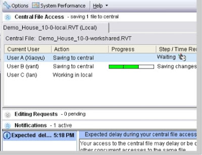
Friday, March 21, 2008
Revit Architecture 2009: Rendering
Revit Architecture 2009 has upgraded many features within its standard package. One being the render tool set. The developers and programmers at Autodesk, have updated the rendering engine to include Mental Ray along with a new interface in the rendering tab.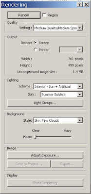
The changes made to the interface are more concise and well laid out. You still have the same options as previous versions of Revit but with more flexibility. If you are wondering how this effects certain workflows such as batch rendering or render farming, Autodesk has yet to include this option. You will still have to export out to another application for this purpose. Below are two images of the same scene from different angles. The first one rendered in Revit Architecture 2008 and the second one in Revit 2009. All settings are default with medium quality as the setting.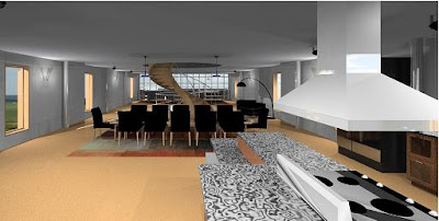
Revit 2008 with Accurender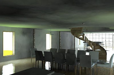
Revit 2009 with Mental Ray
Wednesday, March 19, 2008
Green Architecture
The IES (Integrated Environmental Solutions Virtual Environment) toolkit helps to provide Revit users with the ability to perform an energy analysis that is pretty true to form. While Revit Architecture does hold the sun study tool, IES VE gives designers greater freedom and information in regards to sustainability of the project. In early stages of the design process, I would say anywhere from 50 to 80 percent of changes occur which can dramatically effect the energy output. The IES toolkit will formulate outputs for energy use, carbon use, solar studies, as well as many others. Below is an image of a small complex exported to IES. As you can see, you can set the model properties with building type, system, and place and location.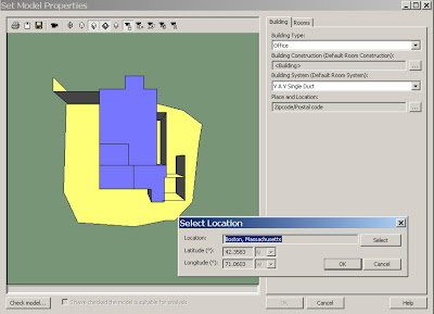
You can tell IES to calculate and create a building analysis in which calculations for areas for walls, floor, ceiling, glazing, and other surface areas will be displayed. You can also choose to view the model in various displays and walkthroughs. Once the model has been checked, you then select the check box "I have checked the model is suitable for analysis". Click OK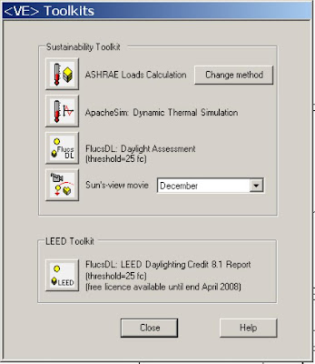
You can then select the Toolkit Icon and run a number of toolkits. For more information on the IES software, visit http://www.iesve.com/content/.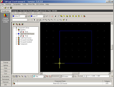
Monday, March 17, 2008
Customized Window Tags That Display Size
As you work in Revit, you may encounter times where the standard families do not suffice. In order to create your own families, you can start from scratch with a blank template, or you can start with an existing family and duplicate it and set it up with different parameters and functions.
1. Within any open file, select a window tag and on the options bar, select Edit Family.
2. This will open the family in another window. Go to File>SaveAs and rename this family at your discretion. For this example I will rename it “Window Size”. Remember to save the family in a network location so that others may access it.
3. In the drawing window, select the lines that make up the hexagon and delete them.
4. Select the parameter, the text piece labeled “1t”. Once you select it, a Select Parameter.. button will appear on the Options toolbar.
5. The Select Parameter dialog box will appear. In the Parameter category window, select Width and select the Format button
6. Uncheck Use Project Settings and switch the Units to Decimal Inches and make sure the Suffix is set to the inch marker. Click OK.
7. Back in the Select Parameter dialog, change the value to 32”. Click OK.
8. Highlight the text piece again and select the Element Properties button. Change the horizontal alignment to Right justification. This is done so that when data is entered, it will move to the left. Click OK.
9. Start the Copy command and copy the parameter over a few inches.
10. Select the right parameter and choose the Select Parameter button on the Options bar.
11. In the Select Parameter dialog box, change the Parameter option to Height. Set the Value to 32”, change the Format to Decimal Inches, and make sure the Suffix is set to the inch marker. Click OK twice to get back to the drawing.
12. Start the Text tool from the Family tab.
13. Place a text piece in between the two parameters and type in a lowercase x.
14. Highlight the “X” text piece and open the Element Properties.
15. In the Element Properties dialog, click on Edit/New and then Duplicate.
16. Give a new name to the text style. For exercise purposes, name the text “3-32”.
17. Change the Text Size to 3/32” and click OK twice to get back to the drawing.
18. In the drawing window, center the pieces so they align together.
19. Select the right parameter and make sure the Horizontal Alignment is set to Left within the Element Properties.
20. Go to File>Save. Close the drawing out.
Thursday, March 13, 2008
I've lost my DWG...now what?
So you say you drawing file was fine yesterday but today you can’t open it? Here are some simple tips that may help you open that file. First, search for the BAK file and rename the extension to DWG. If this doesn’t work, then find any temp file (auto.sv$) and rename the extension to DWG. Hey neither of these steps work! If this occurs, then open a new DWG file and insert the desired file and run the audit command (you may have to hit ESC numerous times as this will halt the regeneration process). Finally, if you have about given up, try the recover command.
Friday, March 7, 2008
...Comparing Apples to Oranges...umm Windows
Macs have come a long way since their inception on April 1st, 1976 . With Mr. Jobs' evangelist like approach, Apple's surge has helped creep its way further into the architecture world. A little over a year ago, Apple introduced its machines with the latest in Intel technology. This allowed Autodesk users to run their products via virtualization or Bootcamp.Of course there are advantages and disadvantages with Bootcamp and Parallels. In this post, I will primarily cover Parallels and how it interacts with Revit. First we need to get the specs out of they way. I currently run off of a Macbook Pro 17 inch Intel Core 2 Duo with 2 GB of memory and a NVIDIA graphics card at 256 VRAM.
Parallels has designed three different methods to run Windows and other platforms. Coherence, full screen, and single window are the three choices or views to select from. Running in coherence mode allows Windows apps to run while working in the Mac environment. Applications execute and populate as if they were in their own native setting.
Here is the setting with Parallels running in full screen. I particularly like this mode because it allows me to use a dual monitor set up where I can utilize both worlds. Depending on how you set this up, you can allow file sharing between the two platforms. I find this view to be best suited for those working with Revit and image/design applications such as the Adobe CS3 package.
Others tend to utilize the single window view. While this method allows you to control Windows programs, it corrals all applications within a single window, which can lead to confusion at some levels. In this mode you cannot maximize views and work efficiently while in Parallels. Below is an image of a single window view.
Finally we come to coherence view. This view works well when you do not have a dual monitor set up. This setting will allow users to execute Windows apps while in OS X. Notice that in this mode, you will be able to access and view the Windows start menu and bar.
No matter which view you work in, Parallels provides users the ability to work in a dual environment. In my experience, Revit has run at optimal performance while experiencing no latency. I am able to work with files in both platforms creating an efficient and productive workflow. If you are wondering about breaking the Autodesk EULA then no worries, I have been advised by Autodesk that it does not break support or license agreements!
Wednesday, March 5, 2008
Massings + (Paramerters * Formulas) = Arghh
Ever look at a design and wonder how the heck was that shape created? Revit Architecture can create many complex shapes through various different methods. One particular option can sometimes, and most of the time, drive a person mad. It feels as if you are the one sitting at the table with the March Hare and the Dormouse because when things don't make sense till you walk away. CHANGE PLACES !!!.
All kidding aside, the way Revit controls parametric formulas and functions are quite remarkable. As you create a simple massing element through the four different options (five now in 2009), it is relatively simple to extrude, sweep, blend, and revolve. What if you need something a little more dynamic. This is where parametric formulas take over. I will use a simple example to illustrate the steps in creating a massing model. I would like to thank Phil Read of Autodesk who has taught me the value of parametric formulas.
In this example I will be using reference lines rather than reference planes. Reference lines give me the option to control planes at four different levels. Please note that this is not a standard way of using parametric formulas but it does give a more basic insight of how these are created.
1. I started a new massing component family and placed in two reference lines extending into the first quadrant from the origin point. I then dimensioned and labeled each A1 and A2 respectively. (These helped to define the Angles of the reference line)
2. Then I created a blended form with my massing tool. When executing the bottom or top of the blend, make sure you set the work plane and select the reference line to which the bottom or top will be associated with. As each sketch is created, I dimensioned them equally and set a Width1 parameter for the bottom sketch and Width2 for the top.
3. Finish the sketch. Go into a 3D view and select the mass and choose edit base. Add vertex connectors and selected the lower left vertex of each face. This rationalizes the form into flat surfaces. Once that is complete, select the mass again and in the element properties, set the value of the First End to Base 1 and Second End to Base 2. This can be done through the radio button.
4. Add parameters: (All are instance parameters)
- Level# (Shared property and an integer)
- Height
- Width
- Linear Change Per Level
- Angular Change Per Level (Should be an Angle parameter)
5. I then entered in my formulas for each category to control the model itself. See below
6. I then saved the family and loaded it into a project that I had open at the time. Place the component or family into the project but make sure you select level 1 with the workplane tool. Use CTRL + C to create copies and select "paste aligned" through the Edit pulldown and select "same place". Create as many instances as you want.
7. Create a new mass schedule and only select the Level# parameter to add. You can the sort by Level # and click OK to create the schedule. Select each row and add in ascending numeric values. Open a 3D view and you should see your model. 
Monday, March 3, 2008
Revit Architecture 2009: Sweep and Blend You Say?
 With the dawn of Revit Architecture 2009, many new features have crept into the BIM platform, thus creating a frenzy among some in the AEC field. As I started Revit 09, I was quickly thrown back to the days of yore. Like my childhood where I would obtain the latest and greatest in gaming, I would discard the manual. I just wanted to play the darn game and learn the old fashion way. 25 plus years later, I am still in that scenario only now its with Revit.
As with all the new tools incorporated in this release, I will try to cover them in subsequent blogs. Today's feature is the Sweep and Blend tool. Have you ever created a spiral staircase and wonder how to get a wall to wrap around the stringer? Ever think there has got to be an easier way to do this? Well in Revit 2009 there is. The swept blend tool combines sweeping and blending into one paint brush so to speak.
There are many different ways to create a wall for the staircase and here is one option. After placing my spiral staircase into the project, I then decided to create an in-place wall family. I selected the outer edge of the right stringer as my 2D path. Then I selected the mass tool with the option of Sweep/Blend (Notice the sketch toolbar is a little different in this mode). I then selected the Sketch Profile 1 for the initial profile and clicked Finish. Same set of steps for the Sketch Profile 2. You can modify the settings for the profile as you could with the previous mass/void settings.
Once the properties were set for the wall, I finished the mass and created the rendering below. This tool allows Reviteers greater flexibility, efficiency, and functionality to create components within their model.
Friday, February 29, 2008
3D Sections
So you’ve decided to go the route of BIM modeling. First and foremost welcome to the future of architectural design. As you are no doubt in awe of the power of Revit, did you know that 3D detailing could be easily created? While in a 3D view, type in VP and check mark the Section Box option. Within the 3D view, stretch and conform the section box to your desired portion Once set, simply type VG and under the Annotation Categories tab, uncheck Section Boxes and voila! You can now add leaders and text to the various elements you wish to detail. It’s just that easy!
Wednesday, February 27, 2008
Why Revit?
Building Information Modeling (BIM) has infiltrated the BSD community and is making its mark with many firms. One of the leading programs is Autodesk’s Revit Building. This program incorporates both 3D modeling and 2D drafting in one. The purpose of this article is not to glorify Revit or denounce AutoCAD, but rather to give insight to the end user on whether or not to at least venture into BIM technology. Revit has many topics worth noting, however, I will just touch upon two..
The Parametric Change Engine
So what exactly is Revit? Revit is much more than a drafting and modeling program. It is based on Building Information Modeling (BIM) technology. Revit, which stands for ‘revise instantly’, uses BIM to create a working, living, breathing model. Using the idea of parametric change technology greatly increases productivity, workflow, and collaboration efforts. Take for example, AutoCAD. Within CAD if a window is deleted or altered, that change has to be manually updated in the file, schedules if any, xref’s and any other views et cetera.
In Revit, users are able to utilize the parametric change technology and not have to worry about updating the model. When a window is deleted or manipulated within a view, it is updated throughout the entire project including schedules, isometric views, sections, elevations, and walkthroughs etc. The parametric change engine allows the user to update one item and not have to worry about changing that same information throughout. I like to say your project has the three C’s in that your design and documentation stay coordinated, consistent, and complete
Worksharing and Projects
In this scenario, a firm has a residential project; one person would not work entirely on every discipline. Within Worksharing, one user will set the basic layouts and components needed for the project start. For example, an exterior shell, interior partitions, furniture layout, HVAC, conveyances, site components, and electrical components are some aspects that go into design. Once the basic layout is structured and laid out, that user will then place each of those components into worksets. Each workset corresponds to a particular design field i.e.: the exterior walls being placed into the “exterior shell” workset. Once that is done, the user will save the project file to a central file. This central file is located on a drive or folder that all users will have access to.
Once the central file is saved, users then access the file on their workstations, and save the central file locally under their username. Each local file can only be altered by that user. When the user opens his/her file, they can “check out” certain worksets. For example, if John is designated to work on the interior partitions, then he can check out the “partitions workset” and only he will be allowed to manipulate the set. Once all amendments are complete, the user will save his/her file to the central file and the updates will be saved to the central file. Each member of the design team will then reload their file thus making it current. The worksharing capabilities go further in depth but you can see how the members of the design team are in sync with one another, thus keeping consistent and coordinated files.
In addition to checking certain worksets out, you are able to “borrow” elements from a users work set. If John is working on the interior partitions and needs to move or delete a window on the exterior shell workset, he can click on an icon and ask permission from that user to borrow that certain element. On the other end, for that user to be notified about the borrowed element, John would have to either call or email the end user and notify him to check his “edit request” icon. This helps to control the project so that no two people are working on the same objects and worksets.
Benefits and Future of Revit
Revit has many features that allow users the flexibility and freedom to design in a manner that does not constrain them to just 2D drawings. BIM technology and the parametric change engine are the two components which make Revit an incredible force in the BSD community. Autodesk has launched the Revit Architecture Suite (RAS) which includes a copy of both Revit Architecture and AutoCAD. Even with new technological advances to BIM, there are a few things to keep in mind. Overcoming the resistance to change and getting users to understand the potential of Revit are two issues firms must deal with. The utilization and functionality of Revit requires an investment and a commitment to take on a new program. Proper training and project management must also be administered. These are some issues to think about when looking into Revit.

